|
Challenges
The Liberty Hi-Railers use TMCC for train operation.
TMCC can provide challenges when operating under demanding conditions such as
those found at Train Shows. Some of those challenges include:
- Multiple clubs operating TMCC on the same frequency (TMCC has only one
frequency!)
- Radio interference from DCC, RC Models, ham radios, FM Live broadcasts, or
just about any other source one can imagine.
- Temporary nature of the layout which includes many connections between
sections. (Connections are not much of a problem for power propagation but
for radio signal propagation it is a whole different ball park!)
- Less than optimal Earth Ground from power source.
- Large size of the modular layout.
- Inherent complexity of Analog Radio Signals!
As you can see, there are quite a number of gremlins that can affect your
TMCC performance adversely. The symptoms of TMCC problems are typically a
flashing headlight which indicates poor TMCC signal strength. Often this
goes with an engine stalling for lack of signal. In the worst case an
engine might take off at full speed because it believes it is running in
conventional mode on 17 volts! Furthermore the problems are typically not just a
single factor as described above, but some combination.
Solutions
Accordingly we have taken a variety of steps to act as countermeasures. Some
elements of being at a show are out of your control, others you can modify and
some require fundamental changes in the TMCC equipment by the train
manufacturers.
- Use a single extension cord to plug the entire layout into 1 outlet. Use a three lamp
outlet tester on that outlet.
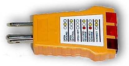 This can detect
a bad ground or other power supply problem.
Also by having the entire layout plugged in to one outlet you avoid any
possible problems with outlets not being in phase with each other. (This
can happen in a large auditorium!) This can detect
a bad ground or other power supply problem.
Also by having the entire layout plugged in to one outlet you avoid any
possible problems with outlets not being in phase with each other. (This
can happen in a large auditorium!)
- Plug the TMCC command base into a power strip without a surge protection
circuit.
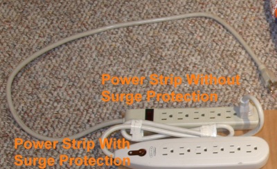 Power strip surge protection circuits tend to drain off your
TMCC signal. You can plug the non-surge protected power strip into
your extension cord. Then plug the TMCC command base into that power
strip. Also plug a surge protected power strip into
it to plug your
transformers into. Power strip surge protection circuits tend to drain off your
TMCC signal. You can plug the non-surge protected power strip into
your extension cord. Then plug the TMCC command base into that power
strip. Also plug a surge protected power strip into
it to plug your
transformers into.
-
Dual power taps. We now route the transformer outputs to two long
six wire cables.
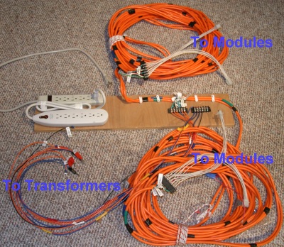 Each cable plugs into the layout at opposite
corners. This helps ensure we have a good injection of the TMCC signal
in two places. (It does not hurt our power distribution either!) The
end of each Power cable is a Y shape with a male and a female 6 pin
connector. This way we can put power in between any two modules with
no special wiring. We just insert the power Y between the normal two
six wire connectors on the modules. Each cable plugs into the layout at opposite
corners. This helps ensure we have a good injection of the TMCC signal
in two places. (It does not hurt our power distribution either!) The
end of each Power cable is a Y shape with a male and a female 6 pin
connector. This way we can put power in between any two modules with
no special wiring. We just insert the power Y between the normal two
six wire connectors on the modules.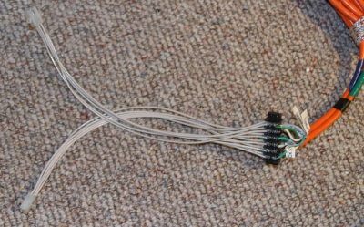 This also has the effect of
directly supplying power to 4 modules. This also has the effect of
directly supplying power to 4 modules.
- The end of each tap is a male and female
6 wire module connector.
- Place the TMCC command base closer to the center of the layout. This
minimizes the distance that any CAB1 remote will be from the command base.
We used to place the command base on the far end of the layout. This
meant that you would have fairly long distance from the opposite end of the
layout. We now place it midway on one of the long sides.
-
Run an earth ground wire around under the layout. We have a long 14
gauge cable that plugs into the third prong of the outlet (Earth ground NOT
the black transformer terminal!!!)
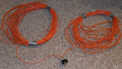
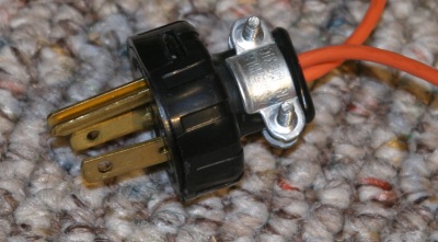
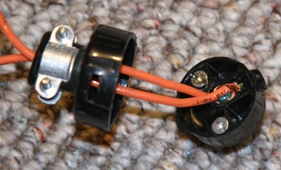 This helps reduce external radio
noise. To build the plug we bought s prong replacement power plug and
wire only the ground prong to our loop of wire. The other two prongs
were taped up and not used. Actually we have two ground wire connected
and we run them in opposite directions. They overlap a little on the
opposite side of the layout. This gives us shortest path to ground
from either direction. This helps reduce external radio
noise. To build the plug we bought s prong replacement power plug and
wire only the ground prong to our loop of wire. The other two prongs
were taped up and not used. Actually we have two ground wire connected
and we run them in opposite directions. They overlap a little on the
opposite side of the layout. This gives us shortest path to ground
from either direction.
- Have a printed list of the engine id numbers your club intends to
use. Bring a few copies, you can exchange them with other clubs at the
same meet to avoid disasters!
- Plea #1 to Lionel - Please change the cabs and command bases to have a
selection of frequencies to operate on, or else add a system ID number to
differentiate multiple systems.
- Plea #2 to Lionel - Please add a 4 way mode switch to all TMCC engines,
the four modes are TMCC Program, Run (automatic select), Run Conventional
Only, Run TMCC Only.
Results
We used the cabling suggestions at the 2004 East Coast Hobby show, the February 2005 Greenberg's
show and the 2005 East Coast Hobby show. For those three shows we experienced zero issues with TMCC signals.
|